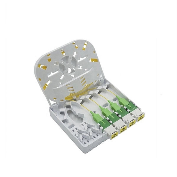
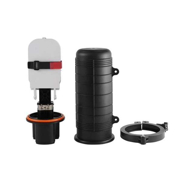
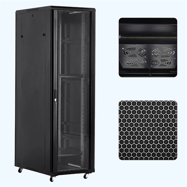
Grounding of the communication terminal box
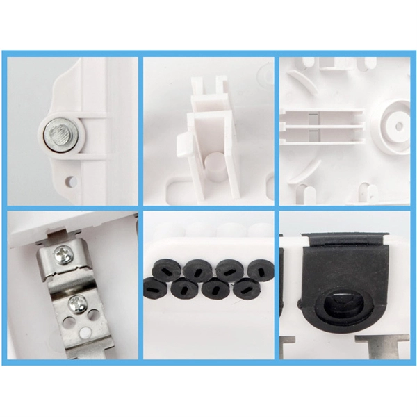
A communication terminal box must be properly grounded and bonded to ensure safety, prevent equipment damage, and maintain signal integrity.Purpose of GroundingGrounding a communication terminal box involves connecting all metallic parts of the telecommunications system to the earth to neutralize potential differences, prevent electrical loops, and protect both personnel and equipment from transients or lightning surges . Proper grounding ensures that all equipment within a telecom room shares a common reference point, minimizing voltage differences that could damage sensitive electronics .Key ComponentsTelecommunication Grounding Busbar (TGB): A copper busbar mounted in the terminal box or rack, serving as the central point for grounding connections .Bonding Conductors: Solid or stranded copper conductors connecting the TGB to the building grounding electrode system, structural steel, water pipes, or other grounding points. Conductors smaller than No. 6 AWG are typically solid, while larger conductors are stranded .Ground Terminal Blocks: Aluminum or copper blocks with stainless steel screws for attaching individual ground wires from equipment or racks .Connectors: Exothermic welds, compression lugs, or two-hole lugs are used to ensure secure, irreversible connections to busbars or grounding electrodes .Grounding Electrodes: Ground rods, plates, or Ufer grounding systems that provide a low-resistance path to earth .Installation GuidelinesSingle-Point Reference: All equipment should be bonded to a single grounding plane to maintain 0 volts potential difference across devices .Shortest and Straightest Path: Grounding conductors should follow the shortest route without unnecessary bends, with a bend radius at least ten times the conductor diameter .Support and Protection: Conductors should be supported at intervals not exceeding 36 inches and protected from mechanical damage. In plenum spaces, EMT conduit may be used .Busbar Mounting: Busbars should be mounted with stand-off brackets providing at least 2 inches of clearance for access, using stainless steel hardware .Bonding Loops: The terminal box should be bonded to the ac utility service entrance, communications cable entrance, and the building grounding system, forming a loop so each element is connected to at least two others .Testing and ComplianceGrounding and bonding must comply with ANSI/TIA-607-B, BICSI TDMM, NEC, and UL standards .Testing should verify continuity, low resistance, and proper bonding of all conductors to protect equipment and personnel .Only qualified personnel, certified by a recognized testing agency, should perform verification tests .SummaryProper grounding of a communication terminal box involves connecting all metallic components to a central grounding busbar, linking it to the building's grounding system, and using secure connectors and conductors. Following standards like ANSI/TIA-607-B and BICSI TDMM, maintaining a single-point reference, and performing thorough testing ensures safety, equipment protection, and reliable network performance .