Finding the fault point in optical cable
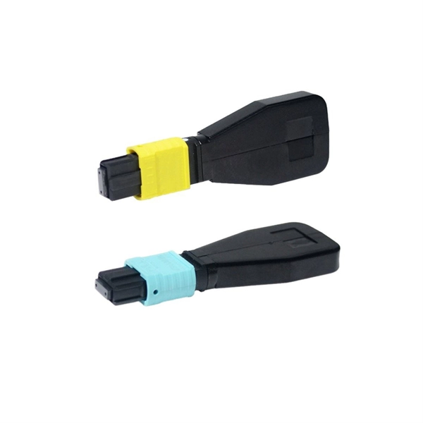
Faults in optical fiber cables can be accurately located using a combination of visual inspection, optical power measurement, and OTDR analysis, depending on the distance and complexity of the link.Key Methods for Fault Detection1. Visual Inspection Start by examining the cable for visible damage such as bends, kinks, breaks, or loose connectors. Inspect entry and exit points, distribution frames, and intermediate connection points. This method is effective for obvious physical faults and can quickly identify issues in short cable runs . 2. Visual Fault Locator (VFL) A red light pen or VFL is used for short-distance faults (≤5 km). The device injects visible red light into the fiber, allowing the technician to see breaks or severe bends directly. Flashing mode improves visibility in bright environments, and fiber identifiers help distinguish individual fibers in dense cables . 3. Optical Power Loss Measurement Using an optical power meter, measure the transmitted and received optical power. Significant drops indicate interruptions, while minor losses may suggest bending or contamination. This method helps pinpoint sections with excessive attenuation . 4. Optical Time Domain Reflectometry (OTDR) OTDR is the most precise tool for long-distance or complex links (>5 km). It measures backscattered and reflected light to detect events such as splices, connectors, and breaks. By analyzing the OTDR trace, the exact distance and characteristics of the fault can be determined. Proper parameter settings, pulse width selection, and curve analysis are critical for accurate results . 5. Continuity and Breakout Box Testing Continuity testing ensures proper optical connections and can detect open or short circuits. Breakout boxes allow access to individual fibers in multi-fiber cables, enabling isolation and testing of specific fibers to narrow down the fault location .Practical ConsiderationsCable Design and Excess Fiber: Optical cables often include excess fiber in buffer tubes, which can affect distance measurements. Accurate fault location requires accounting for this excess length .OTDR Limitations: OTDR measurements have inherent uncertainties (±1% typical), influenced by refractive index variations, cable take-up factors, and route deviations. Using sheath length markers and averaging multiple fibers can improve accuracy .Scenario-Based Approach: For home or enterprise troubleshooting, start with simple checks like restarting modems and verifying connections. Use VFL for short faults, optical power meters for attenuation issues, and OTDR for complex or long-distance faults .Recommended WorkflowPerform a visual inspection for obvious damage.Use a VFL for short-distance faults.Measure optical power to identify sections with abnormal loss.Apply OTDR for precise distance measurement and fault characterization.Use continuity testing or breakout boxes to isolate individual fibers if needed.Adjust for cable design factors and verify results with multiple fibers or markers. By combining these methods, technicians can efficiently and accurately locate faults in optical fiber cables, minimizing downtime and ensuring network reliability .