Selection of Instrument Cable Tray Specifications
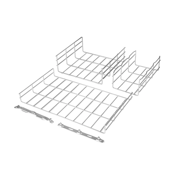
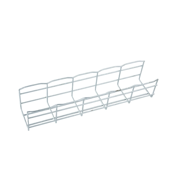
Select shielded, twisted-pair instrumentation cables and properly sized, dedicated cable trays to ensure signal integrity, mechanical protection, and compliance with NEC/IEC standards.Instrumentation Cable SelectionCable Type and Construction: Instrumentation cables are designed to carry low-level signals such as 4–20 mA analog loops, thermocouple outputs, RTD measurements, or digital fieldbus data. They typically feature twisted pairs or triads, shielding (foil, braid, or both), and a drain wire to minimize electromagnetic interference (EMI) and radio-frequency interference (RFI) from nearby power equipment or VFDs ( ). Conductor Size:18 AWG is common for PLTC and tray cable applications.22–24 AWG is used for RS-485 and fieldbus circuits.16 AWG is reserved for long loops or higher current industrial instrumentation ( ). Insulation Material:PVC: General-purpose, moisture-resistant, rated 75–90°C.XLPE: Higher temperature and moisture resistance, suitable for outdoor or wet locations.FEP: High-temperature and plenum-rated applications.PE: Low capacitance for high-speed data and fieldbus applications ( ). Voltage Rating:PLTC-rated cables: 300V, NEC Article 725.TC-rated cables: 600V, NEC Article 336, can share trays with power conductors if necessary ( ). Shielding Considerations: Proper shielding is critical to prevent signal degradation from nearby power lines or motors. Twisted pairs with foil or braid shields are standard, and a drain wire should be grounded at one end to shunt noise ( ).Cable Tray Selection and InstallationTray Types:Ladder trays: Ideal for long runs with good airflow.Perforated trays: Medium load, moderate protection.Solid-bottom trays: Protect delicate cables from dust and moisture.Wire mesh trays: Flexible routing, often used in control rooms or data centers ( ). Material Selection:Steel: Strong, durable, suitable for heavy-duty applications.Aluminum: Lightweight, corrosion-resistant, suitable for outdoor or corrosive environments.Stainless steel (AISI 316L): High corrosion resistance for harsh chemical environments ( ). Tray Sizing and Fill:Use the Area Fill Method for single-conductor cables and Diameter Fill Method for multi-conductor cables.NEC guidelines typically limit multi-conductor cables to 40% of the tray's internal cross-sectional area for solid-bottom trays to allow heat dissipation ( ).Ensure trays can support the combined weight of all cables and allow for future expansion. Separation from Power Cables:Keep instrumentation and power cables in separate trays or compartments to prevent inductive coupling and EMI ( ).If sharing a tray, use TC-rated cables and maintain proper shielding. Installation Best Practices:Support cables along their entire run to reduce mechanical stress ( ).Avoid unnecessary cable joints; use approved junction boxes.Maintain adequate spacing and grounding for shielded cables.Consider environmental factors such as moisture, UV exposure, and chemical corrosion when selecting cable insulation and tray material ( ).SummaryFor reliable instrumentation signal transmission:Choose twisted-pair, shielded cables with appropriate conductor size and insulation.Select dedicated cable trays with proper material, type, and sizing.Follow NEC/IEC fill and separation guidelines to prevent EMI and overheating.Ensure mechanical support, grounding, and environmental protection for long-term system reliability. This approach ensures signal integrity, safety, and compliance in industrial and process plant installations.